IRF7534D1TR 데이터 시트보기 (PDF) - International Rectifier
부품명
상세내역
일치하는 목록
IRF7534D1TR Datasheet PDF : 8 Pages
| |||
PD -93864
IRF7534D1
q Co-packaged HEXFET® power
MOSFET and Schottky diode
q Ultra Low On-Resistance
MOSFET
q Trench technology
q Micro8TM Footprint
q Available in Tape & Reel
Description
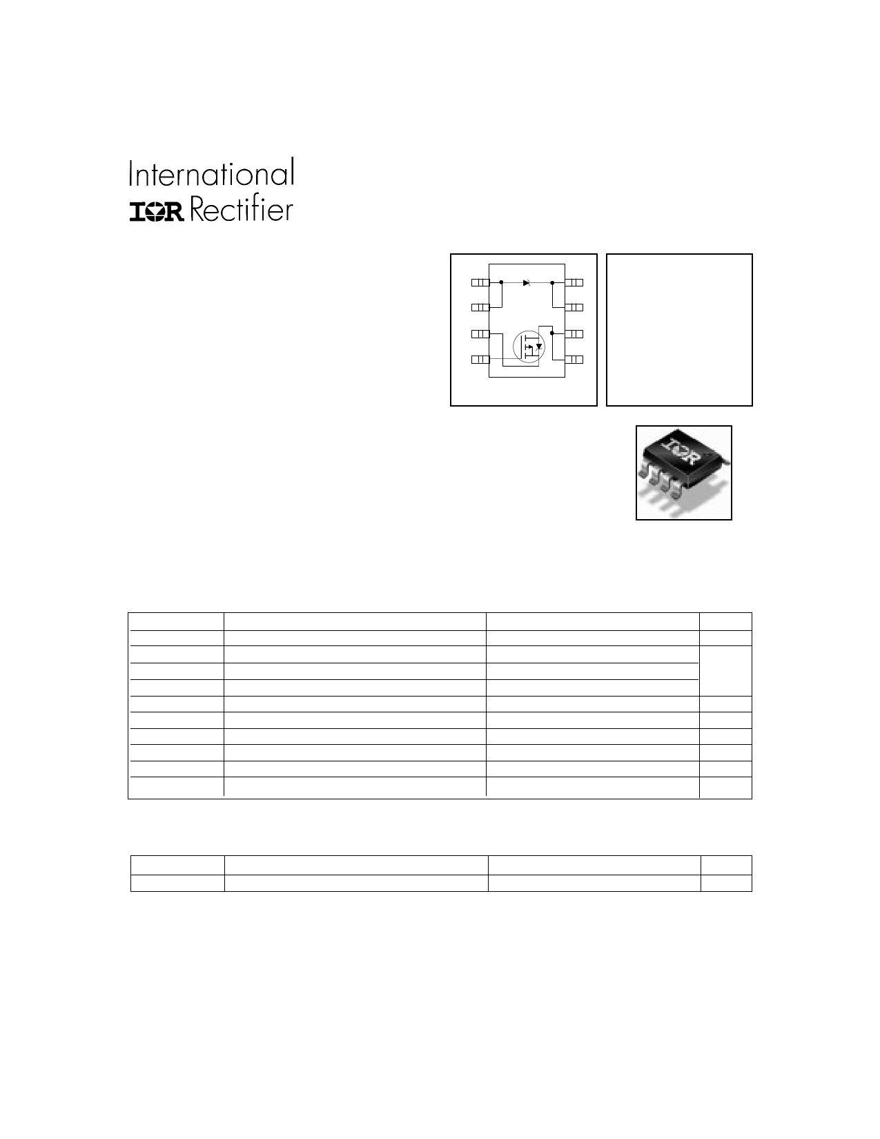
FETKY MOSFET & Schottky Diode
A
1
A
2
8
K
7
K
VDSS = -20V
S
3
6 D RDS(on) = 0.055Ω
G
4
5
D
Schottky Vf=0.39V
Top View
The FETKY family of co-packaged MOSFETs and Schottky diodes offers the designer
an innovative, board space saving solution for switching regulator and power
management applications. International Rectifier utilizes advanced processing
techniques to achieve extremely low on-resistance per silicon area. Combining this
technology with International Rectifier’s low forward drop Schottky rectifiers results in
an extremely efficient device suitable for use in a wide variety of portable electronics
applications, such as cell phones, PDAs, etc.
The Micro8TM package makes an ideal device for applications where printed circuit
board space is at a premium. The low profile (<1.1mm) of the Micro8TM will allow it to
fit easily into extremely thin application environments such as portable electronics
Absolute Maximum Ratings
Parameter
VDS
ID @ TA = 25°C
ID @ TA = 70°C
IDM
PD @TA = 25°C
PD @TA = 70°C
Drain-Source Voltage
Continuous Drain Current, VGS @ -4.5V
Continuous Drain Current, VGS @ -4.5V
Pulsed Drain Current
Maximum Power Dissipation
Maximum Power Dissipation
Linear Derating Factor
VGS
dv/dt
Gate-to-Source Voltage
Peak Diode Recovery dv/dt
TJ , TSTG
Junction and Storage Temperature Range
Max.
-20
-4.3
-3.4
-34
1.25
0.8
10
± 12
1.1
-55 to + 150
Micro8™
Units
V
A
W
W
mW/°C
V
V/ns
°C
Thermal Resistance
Parameter
Max.
Units
RθJA
Maximum Junction-to-Ambient
100
Notes:
Repetitive rating – pulse width limited by max. junction temperature (see Fig. 9)
ISD ≤ -1.2A, di/dt ≤ 100A/µs, VDD ≤ V(BR)DSS, TJ ≤ 150°C
Pulse width ≤ 300µs – duty cycle ≤ 2%
When mounted on 1 inch square copper board to approximate typical multi-layer PCB thermal resistance
°C/W
www.irf.com
1
3/22/00
Share Link: 