A6850 데이터 시트보기 (PDF) - Altera Corporation
부품명
상세내역
일치하는 목록
A6850 Datasheet PDF : 15 Pages
| |||
a6850 Asynchronous Communications Interface Adapter Data Sheet
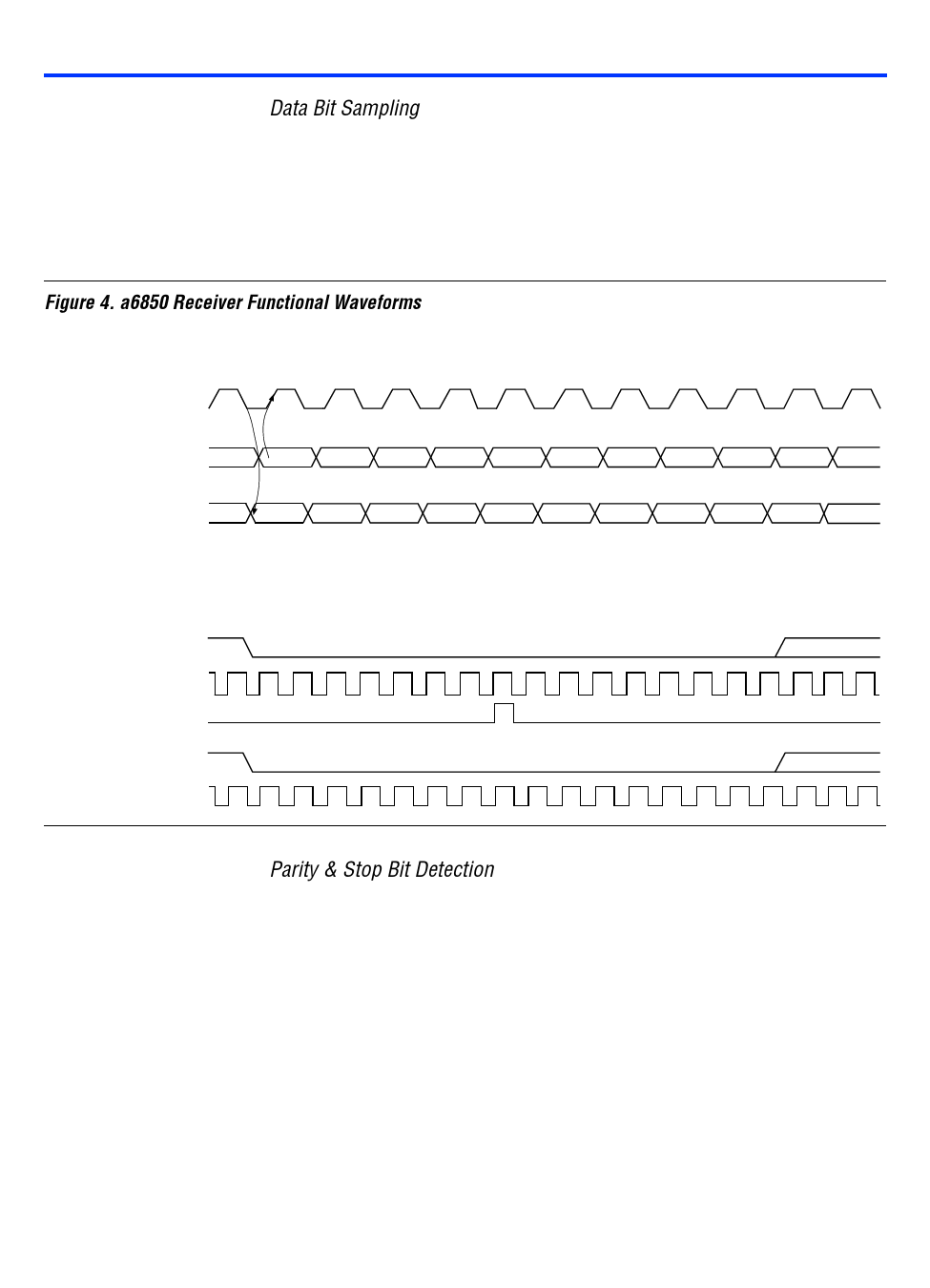
Data Bit Sampling
After detecting a logic low, the a6850 samples and shifts the data into the
input shift register. Data bit sampling occurs on every rising edge in
divide-by-1 mode, every 16 rising edges in divide-by-16 mode, and every
64 rising edges in divide-by-64 mode. Each time a bit is sampled, parity is
calculated for future error detection. See Figure 4.
Figure 4. a6850 Receiver Functional Waveforms
Divide-by-1 Mode
rxclk
or txclk
rxdata
Sampled on rising edge of rxclk
txdata
Driven from falling edge of txclk
Divide-by-16 Mode
rxdata
rxclk
Sampling Pulse
txdata
txclk
Start Bit
Start Bit
Data Bit
Data Bit
Parity & Stop Bit Detection
The a6850 counts the number of data bits as it shifts. When the number of
data bits received matches the number specified in the control register, the
a6850 expects either a parity bit or a stop bit.
If parity is enabled, the a6850 samples for the parity bit, which is then
processed for parity. However, if parity is not enabled, the a6850 samples
for a stop bit (i.e., logic high). If a logic low is sampled, the fe bit is set in
the status register.
Altera Corporation
91
Share Link: 