AIC1732 데이터 시트보기 (PDF) - Analog Intergrations
부품명
상세내역
일치하는 목록
AIC1732 Datasheet PDF : 6 Pages
| |||
AIC1732
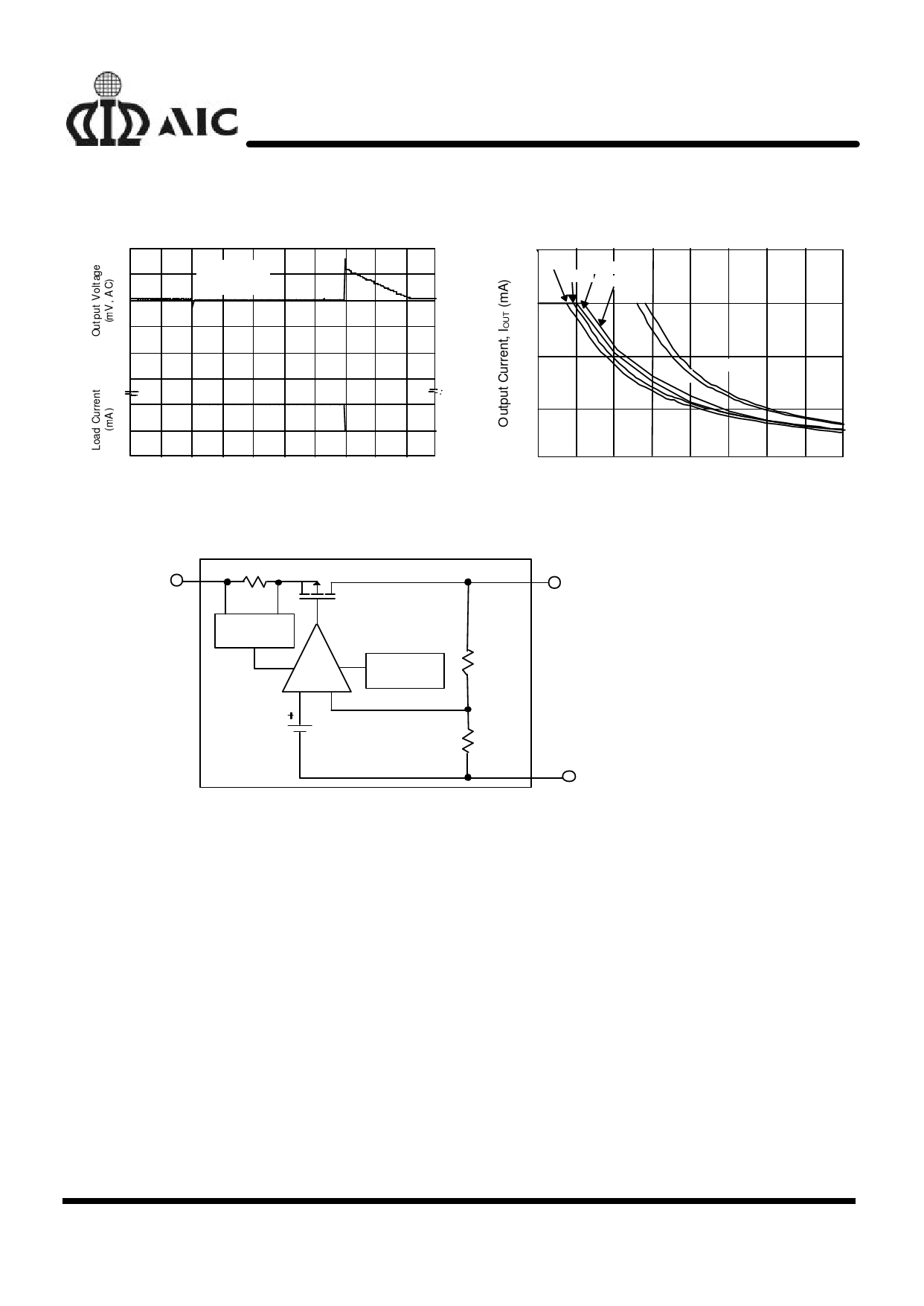
n TYPICAL PERFORMANCE CHARACTERISTICS (Continued)
Load Transient Response
100
COUT= 1 µF
V OUT= 5 .2 V
0
-1 0 0
-2 0 0
150
0. 1
0
0.5 1. 0
1. 5
2.0 2.5 3.0
3.5
4.0 4.5 5.0
Time (mS)
n BLOCK DIAGRAM
Recommended Max. Output Current v.s. Input Voltage
400
3. 3 V
3. 7 V
3.5V 3.8V
300
200
5.2V
5V
100
0
4
5
6
7
8
9
10
11
12
Input Voltage VIN (V)
VIN
CURRENT
LIMITING
-
ERROR
AMP
+
THERMAL
SHUTDOWN
1.235V
- Reference
n PIN DESCRIPTION
VOUT PIN - Output pin.
GND PIN - Power GND.
VIN PIN - Power Supply Input.
n APPLICATION INFORMATIONS
A 1µF (or greater) capacitor is required between
the AIC1732 output and ground for stability.
Without this capacitor the part will oscillate. Even
though most types of capacitor may work, the
equivalent series resistance (ESR) should be held
to 5Ω or less if Aluminum electrolytic type is used.
Many Aluminum electrolytics have electrolytes
that freeze at about -30°C, so solid tantalums are
recommended for operation below -25°C. The
VOUT
GND
value of this capacitor may be increased without
limit.
A 0.1µF capacitor (or greater) should be placed
from the AIC1732 input to ground if the lead
inductance between the input and power source
exceeds 500nH (approximately 10 inches of trace).
5
Share Link: 