AD8340 데이터 시트보기 (PDF) - Analog Devices
부품명
상세내역
일치하는 목록
AD8340 Datasheet PDF : 20 Pages
| |||
AD8340
Data Sheet
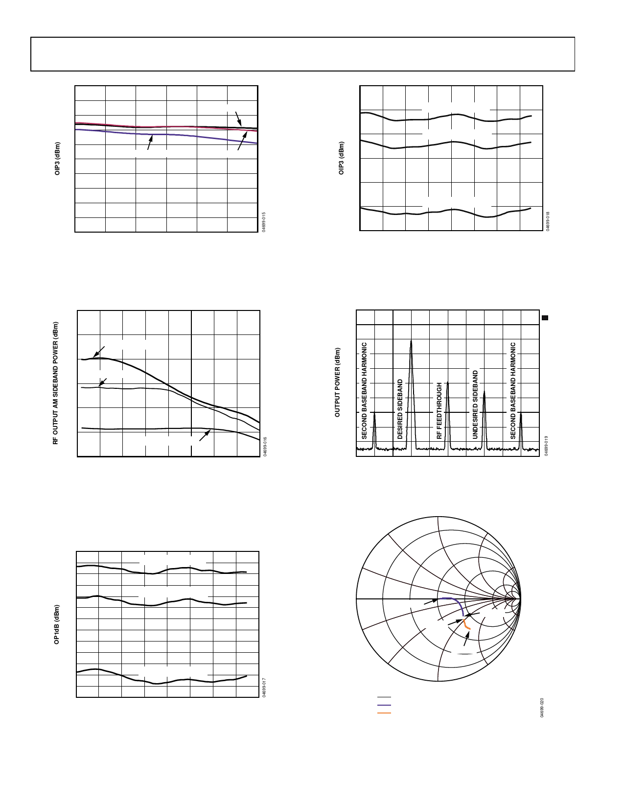
30
28
26
24
22
20
18
16
14
12
10
700
TEMP = –40°C
TEMP = +85°C
TEMP = +25°C
750
800
850
900
950
1000
FREQUENCY (MHz)
Figure 15. Output IP3 vs. Frequency and Temperature, Maximum Gain, I Only
0
–5
1V p-p BB INPUT
–10
500mV p-p BB INPUT
–15
–20
–25
200mV p-p BB INPUT
–30
0
50 100 150 200 250 300 350 400
FREQUENCY (MHz)
Figure 16. I/Q Modulation Bandwidth vs. Baseband Magnitude
14
12
GAIN SETPOINT = 1.0
10
8
6
GAIN SETPOINT = 0.5
4
2
0
–2
–4
–6
–8
GAIN SETPOINT = 0.1
–10
–12
0
45
90 135 180 225 270 315 360
PHASE SETPOINT (Degrees)
Figure 17. Output 1dB Compression Point vs. Gain and Phase Setpoints
30
25
GAIN SETPOINT = 1.0
20
GAIN SETPOINT = 0.5
15
10
GAIN SETPOINT = 0.1
5
0
0
45
90 135 180 225 270 315 360
PHASE SETPOINT (Degrees)
Figure 18. Output IP3 vs. Gain and Phase Setpoints, 2.5 MHz Carrier Spacing
REF LVL
0 dBm
0
–10
–20
–30
–40
–50
–60
–70
–80
–90
RBW 30kHz RF ATT 20dB
VBW 30kHz MIXER –10dBm
SWT 100ms UNIT
dBm
A
1 RM
–100
CENTER 880 MHz
500 kHz/DIV
FREQUENCY (MHz)
SPAN 5 MHz
Figure 19. Single-Sideband Performance, 880 MHz, −10 dBm RF Input;
1 MHz, 500 mV p-p Differential BB Drive
90
120
60
150
30
180
210
1.5GHz
1.5GHz
0
500MHz
330
500MHz
240
300
270
IMPEDANCE CIRCLE
S11 RF PORT WITH 5.6nH INDUCTORS
S11 RF PORT WITHOUT INDUCTORS
Figure 20. Input and Output Impedance Smith Chart
(with Frequency Markers)
Rev. C | Page 8 of 20
Share Link: 